One of the projects I am now working on: a motorcycle telemetry unit
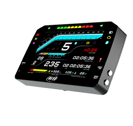
An example motorcycle telemetry unit, developed by AimTechnologies.
Context
I ride a 2007 Yamaha YZF-R6, a 599cc supersport motorcycle that is ~20 years old. This motorcycle was designed and produced before Anti-Brakelock System (ABS), Traction Control (TC), and Lean Angle sensors. For track usage, which I intend on using this bike for, it is helpful (mostly fun, but also helpful…) to have recorded information about the lean angle and G-forces of the motorcycle throughout the course. For example, a modern superbike like the Honda CBR1000RR-R Fireblade has this system built into its onboard computer. My 20 year old sportbike does not. To remedy this, I am making my own.
All information about this project, including software, 3D models, and circuit diagrams, will be open-sourced for people to build their own!
Problem Statement
I want to be able to track and monitor my motorcycle’s lean angle and experienced G-forces, both live and through my computer after the ride.
Project System Specifications
A motorcycle telemetry unit that:
- Shows the data live through a screen
- Does not rely on battery life
- Accurately measures G-force and lean angle
- Saves the data in a way that a computer can process and visualize
Hardware to Accomplish This
Inertial Measurement Unit (IMU): The IMU measures the G-force and lean angle via an accelerometer and a G-force sensor, and produces a digital output. The product I chose for this project is the Arduino Nano 33 BLE v2. This nano microcontroller has a 9-axis IMU built in, and can do basic mathematical calculations to convert the digital output of the sensors into human-readable/relevant data (such as a lean angle from a digital sensor range of 0-255). The main reason I chose this microcontroller is because I already had one laying around for another project, and wanted to conserve my budget for this project. A more robust approach would use a standalone IMU sensor that is lightweight, and do all the math on the main microcontroller.
Display: The display is an LCD screen that displays the live data from the IMU/Arduino Nano, and produces a visualization that can be easily/quickly interpreted by the rider. The screen I chose for this is the Waveshare ESP32-S3 2.8inch touch-screen. The ESP32-S3 is a System-on-Chip (SoC, basically a micro-computer) that is (hopefully) capable of producing the visualization/animation I want to create with the data, such as a G-force “circle” (G-G diagram). I chose this because:
- The LCD should perform well under direct-sunlight conditions
- The ESP32-S3 should be powerful enough to handle basic animations
- It is easily connectable to the Arduino Nano
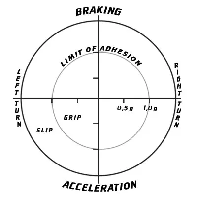
An example G-G diagram. A dot would appear in a cartesian format, based on the forward/backward acceleration and left/right acceleration. Source
Other Relevant Hardware:
- 9-36v to 5v buck converter: Needed to turn the 12ish volts coming from the battery/bike charging system into a stable 5v to safely power the Arduino and ESP32 modules
- 1A fuses: To safely power the electronics in case of a current surge
My Progress
So far, I have tested the IMU on the Arduino Nano and am in the process of turning it into more human-readable information. In the coming week, I will receive and test the ESP32 screen module and start testing visualization strategies.
The Future of this Project
In the future, I want to incorporate a GPS module in order to:
- Track 1/4 mile, 1/2 mile, etc times
- 0-60mph times
- Associate a GPS location to lean angle and G-force for track day analysis
I also want to be able to use a centralized clock system of sorts in order to sync GoPro footage to the telemetry data. I want to make this an All-In-One open-source telemetry system.